Home

Előzetes eladás házifeladatot csinálni Minimális ideal inverter megragad Rendellenes özvegy

a) CMOS inverter circuit. (b) Simplified view of CMOS inverter... |  Download Scientific Diagram
a) CMOS inverter circuit. (b) Simplified view of CMOS inverter... | Download Scientific Diagram

Graphical representation of the equilibrium point of the PFGA. (a)... |  Download Scientific Diagram
Graphical representation of the equilibrium point of the PFGA. (a)... | Download Scientific Diagram

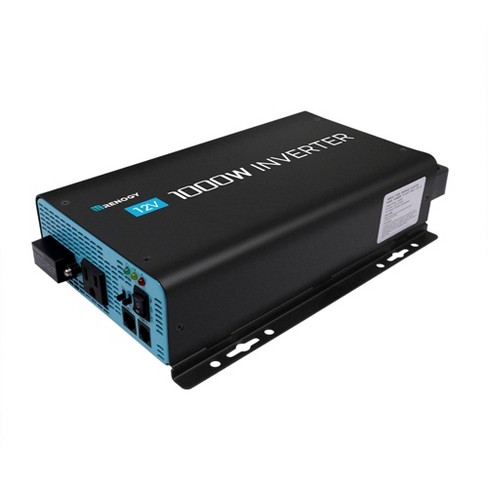
Renogy 1000w 12v Pure Sine Wave Inverter With Power Saving Mode Ideal For  Use In Vans, Semi-trucks, 5th Wheels, Cabin, Or Any Remote Location, Black  : Target
Renogy 1000w 12v Pure Sine Wave Inverter With Power Saving Mode Ideal For Use In Vans, Semi-trucks, 5th Wheels, Cabin, Or Any Remote Location, Black : Target

Instrumentation Pro: MOS Inverters: Static Characteristics

IDEAL POWER- UPS, AVR, IDEAL UPS, IDEAL AVR, Inverter, Online UPS, DC UPS,  iPhone Charger, Solar, Standby UPS, Off Line UPS, Line Interactive UPS,  OEM/ODM Manufacturer - INVISIMO Series 1000VA-3200VA
IDEAL POWER- UPS, AVR, IDEAL UPS, IDEAL AVR, Inverter, Online UPS, DC UPS, iPhone Charger, Solar, Standby UPS, Off Line UPS, Line Interactive UPS, OEM/ODM Manufacturer - INVISIMO Series 1000VA-3200VA

VLSI Design - MOS Inverter

IDEAL EXPERT MIG 250 4x4 PFC SYNERGIC Inverter welding machine MIG MAG 230  V | eBay
IDEAL EXPERT MIG 250 4x4 PFC SYNERGIC Inverter welding machine MIG MAG 230 V | eBay

Explain transfer Characteristics for NMOS inverter showing different  regions. What is the effect of variation in (W/L) ratio .
Explain transfer Characteristics for NMOS inverter showing different regions. What is the effect of variation in (W/L) ratio .

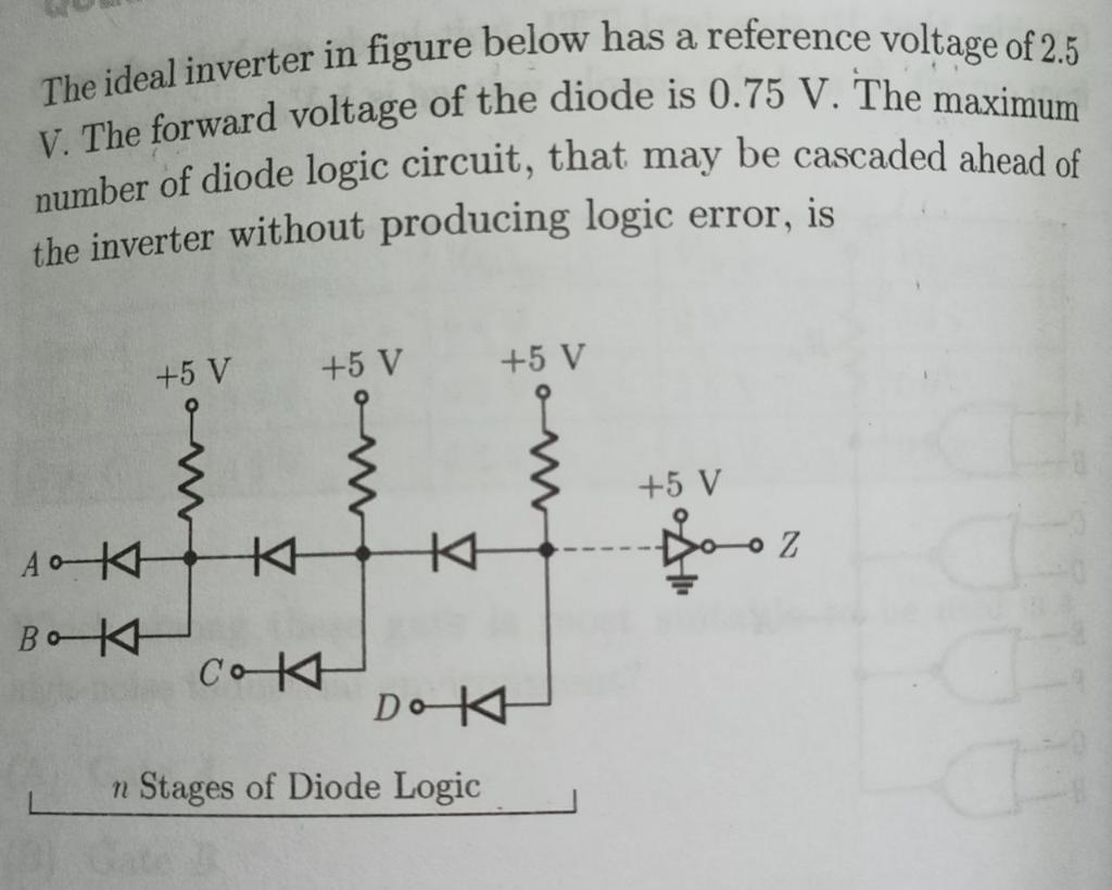
Solved The ideal inverter in figure below has a reference | Chegg.com

Amazon.com: 12V 24V to 220V Solar Inverter High Power, Solar Power Inverter  Sine Wave Inverter Built in Cooling Fan, AC Outlets USB Charging Ports Ideal  12V to 220V,10000W : Patio, Lawn &
Amazon.com: 12V 24V to 220V Solar Inverter High Power, Solar Power Inverter Sine Wave Inverter Built in Cooling Fan, AC Outlets USB Charging Ports Ideal 12V to 220V,10000W : Patio, Lawn &

Ideal noise-free CMOS inverter | Download Scientific Diagram

IDEALPLUSING Hot Sale 5000 Watts Off Grid Solar Pure Sine Wave Inverter

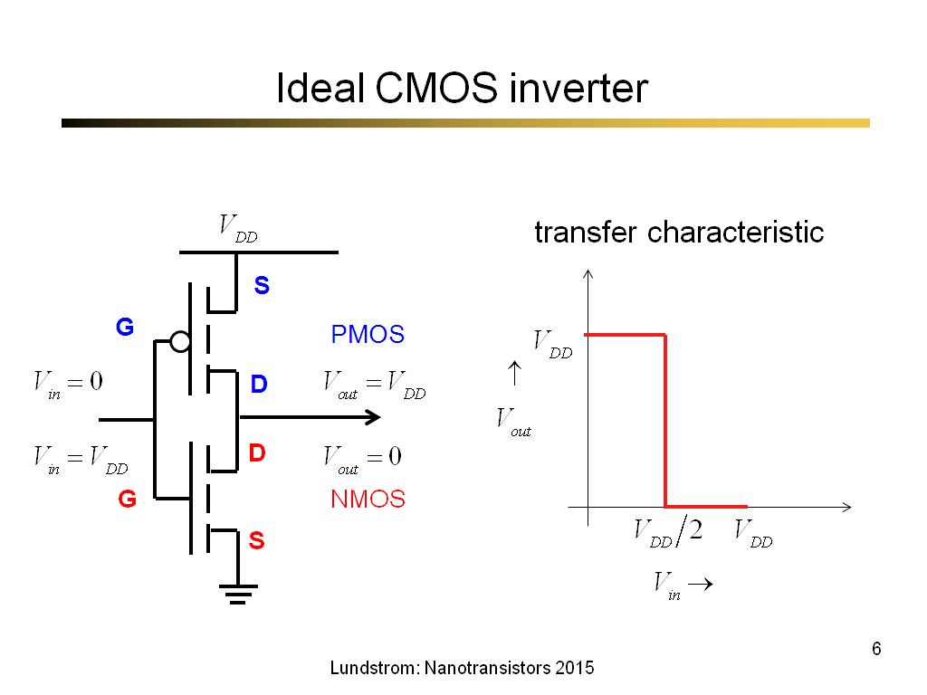
nanoHUB.org - Courses: nanoHUB-U: Fundamentals of Nanotransistors, 2nd  Edition: Spring 2016
nanoHUB.org - Courses: nanoHUB-U: Fundamentals of Nanotransistors, 2nd Edition: Spring 2016

SOLVED: 2.[Erickson 19.9 (old version)/22.9 (new version)] The LLC inverter  shown below operates at the switching frequency fs = 100 kHz. All elements  are ideal. Ls = 0.4 F Lp = 2.5
SOLVED: 2.[Erickson 19.9 (old version)/22.9 (new version)] The LLC inverter shown below operates at the switching frequency fs = 100 kHz. All elements are ideal. Ls = 0.4 F Lp = 2.5

Ideal™ TIG DC HF PULSE Inverter Welder 200Amp Welding machine MMA Stainless  INOX | eBay
Ideal™ TIG DC HF PULSE Inverter Welder 200Amp Welding machine MMA Stainless INOX | eBay

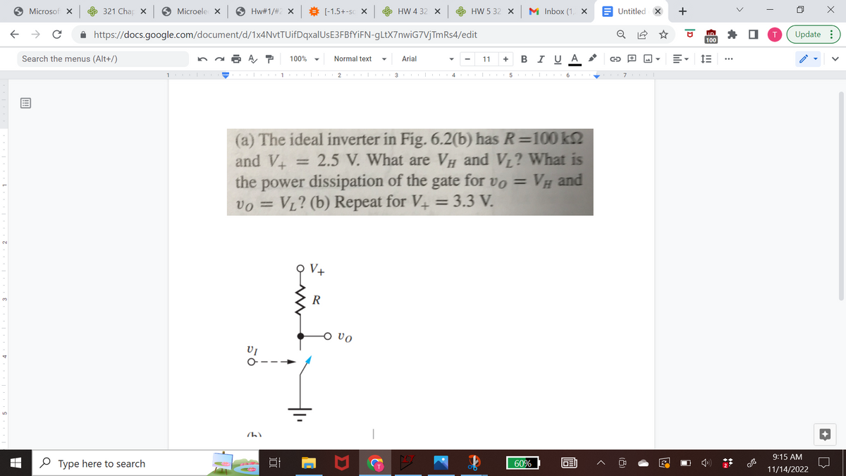
Answered: (a) The ideal inverter in Fig. 6.2(b)… | bartleby

power_IPP60R074C6_325V_H-Bridge_Inverter_ideal_PWM.tsc - TINACloud

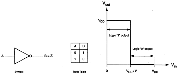
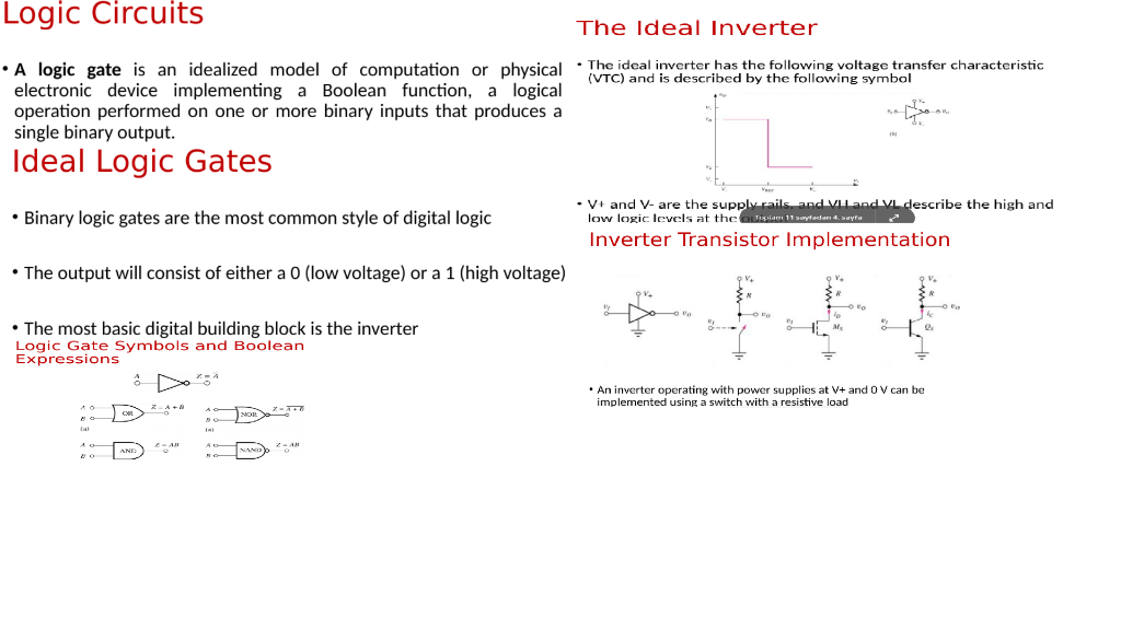
Solved Logic Circuits The Ideal Inverter • A logic gate is | Chegg.com

Amazon.com: 1500W Pure Sine Wave Power Inverter with LED Meter of Input  Voltage and Output Instant Power Ideal for car, Van and Solar System. :  Automotive
Amazon.com: 1500W Pure Sine Wave Power Inverter with LED Meter of Input Voltage and Output Instant Power Ideal for car, Van and Solar System. : Automotive

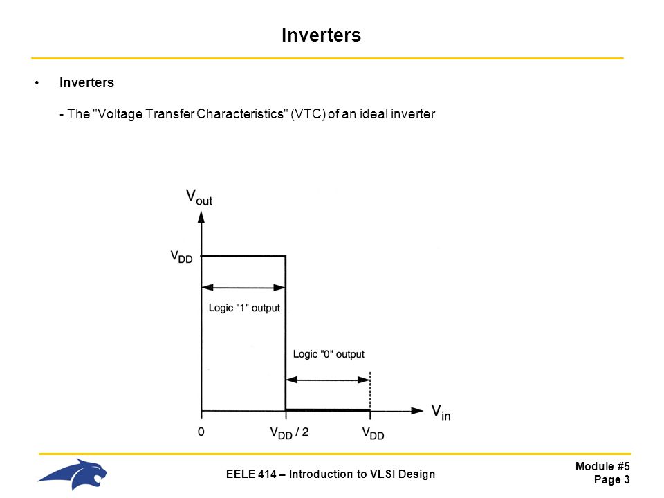
EELE 414 – Introduction to VLSI Design - ppt download

In a 3 ϕ inverter circuit shown in the figure, the load is balanced and the  inverter is operating in 180∘ conduction mode. All the devices are assumed  to be ideal. If
In a 3 ϕ inverter circuit shown in the figure, the load is balanced and the inverter is operating in 180∘ conduction mode. All the devices are assumed to be ideal. If

Ideal three phase inverter | Download Scientific Diagram

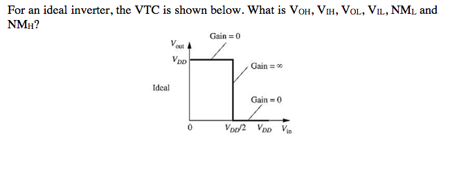
Solved For an ideal inverter, the VTC is shown below. What | Chegg.com

The Design of Bandpass Filters Considering Frequency Dependence of Inverters